03. Robot Model: Basic Setup
Robot Model: Basic Setup

A blind robot
As a roboticist or a robotics software engineer, building your own robots is a very valuable skill and offers a lot of experience in solving problems in the domain. Often, there are limitations around building your own robot for a specific task, especially related to available resources or costs.
That's where simulation environments are quite beneficial. Not only do you have freedom over what kind of robot you can build, but you also get to experiment and test different scenarios with relative ease and at a faster pace. For example, you can have a simulated drone to take in camera data for obstacle avoidance in a simulated city, without worrying about it crashing into a building!
You previously learned about the Unified Robot Description Format (URDF) in Term-1. In this section, you will build a very basic mobile robot model by creating its own URDF file!
Robot URDF
Let's first create a new folder in your package directory and an empty xacro file for the robot's URDF description.
$ cd /home/workspace/catkin_ws/src/udacity_bot/
$ mkdir urdf
$ cd urdf
$ nano udacity_bot.xacro
There are several approaches or design methodologies you can consider when creating your own robot. For a mobile robot, you can break the concept down into some basic details - a robot base, wheels, and sensors.
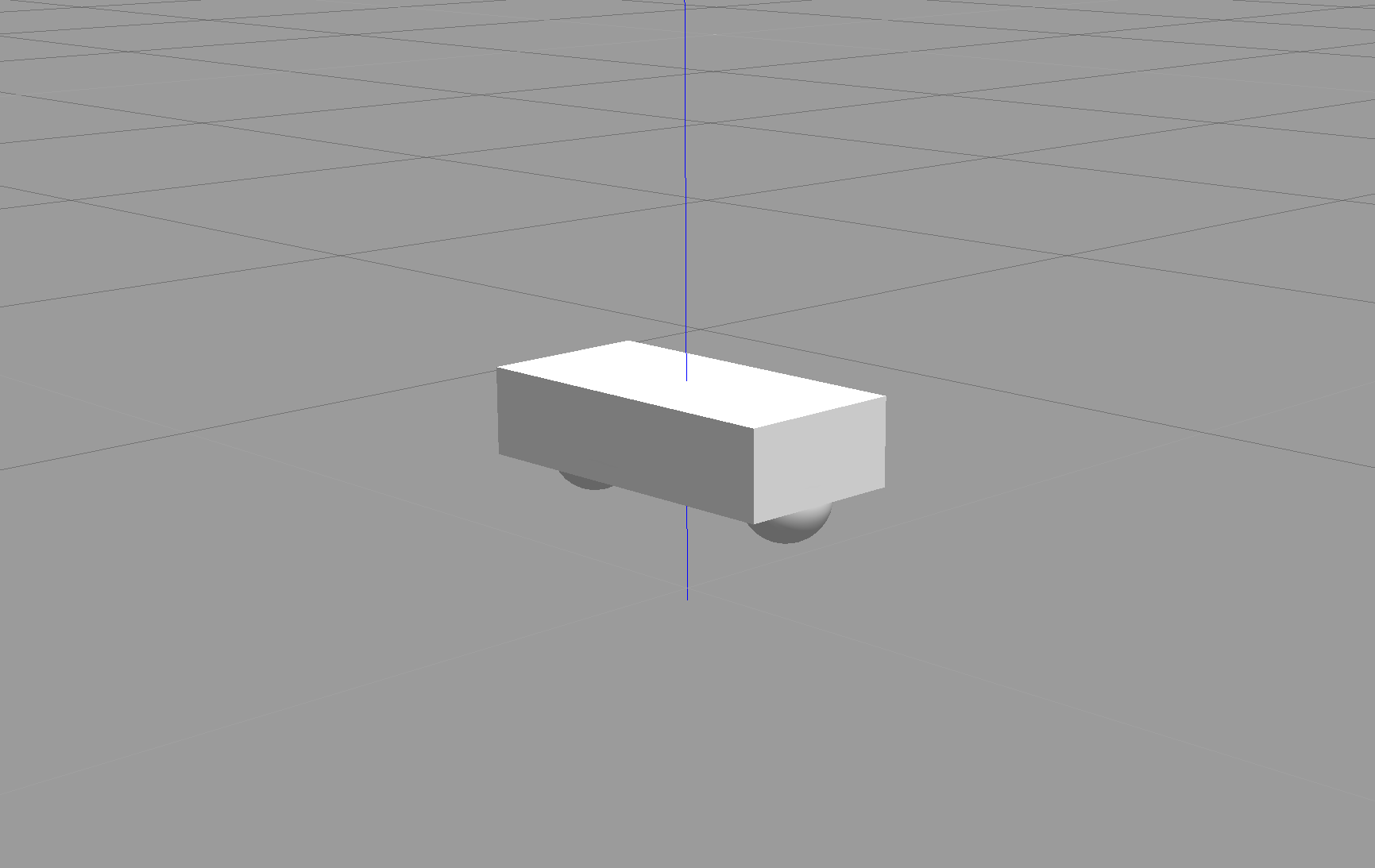
For this model, we will create a cuboidal base with two caster wheels. The caster wheels will help stabilize this model. They aren't always required, but it can help with weight distribution, preventing your robot from tilting along the z-axis at times.
Copy the following code into your udacity_bot.xacro file. Take some time and go through the code as well.
<?xml version='1.0'?>

<robot name="udacity_bot" xmlns:xacro="http://www.ros.org/wiki/xacro">

  <link name="robot_footprint"></link>

  <joint name="robot_footprint_joint" type="fixed">
    <origin xyz="0 0 0" rpy="0 0 0" />
    <parent link="robot_footprint"/>
    <child link="chassis" />
  </joint>

  <link name='chassis'>
    <pose>0 0 0.1 0 0 0</pose>

    <inertial>
      <mass value="15.0"/>
      <origin xyz="0.0 0 0" rpy=" 0 0 0"/>
      <inertia
          ixx="0.1" ixy="0" ixz="0"
          iyy="0.1" iyz="0"
          izz="0.1"
      />
    </inertial>

    <collision name='collision'>
      <origin xyz="0 0 0" rpy=" 0 0 0"/>
      <geometry>
        <box size=".4 .2 .1"/>
      </geometry>
    </collision>

    <visual name='chassis_visual'>
      <origin xyz="0 0 0" rpy=" 0 0 0"/>
      <geometry>
        <box size=".4 .2 .1"/>
      </geometry>
    </visual>


    <collision name='back_caster_collision'>
      <origin xyz="-0.15 0 -0.05" rpy=" 0 0 0"/>
      <geometry>
        <sphere radius="0.0499"/>
      </geometry>
    </collision>

    <visual name='back_caster_visual'>
      <origin xyz="-0.15 0 -0.05" rpy=" 0 0 0"/>
      <geometry>
        <sphere radius="0.05"/>
      </geometry>
    </visual>

    <collision name='front_caster_collision'>
      <origin xyz="0.15 0 -0.05" rpy=" 0 0 0"/>
      <geometry>
        <sphere radius="0.0499"/>
      </geometry>
    </collision>

    <visual name='front_caster_visual'>
      <origin xyz="0.15 0 -0.05" rpy=" 0 0 0"/>
      <geometry>
        <sphere radius="0.05"/>
      </geometry>
    </visual>

  </link>

</robot>
In the above code, we have a single link, with the name defined as "chassis", encompassing the base as well as the caster wheels. Each link has specific elements, such as the inertial or the collision elements. You can quickly recap some details on these elements covered in this lesson from Term-1. The chassis is a cuboidal (or box), whereas the casters are spherical as denoted by their <geometry> tags. Each link (or joint) has an origin (or pose) defined as well. Every element of that link or joint will have its own origin, which will be relative to the link's frame of reference.
For this base, as the casters are included as part of the link (for stability purposes), there is no need for any additional links to define the casters, and therefore no joints to connect them. The casters do, however, have friction coefficients defined for them, and are set to 0, to allow for free motion while moving.
Before we move on to the next part of this setup, let's quickly try to launch this model in Gazebo!
Launch Model
Create a new launch file that will help load the URDF file.
$ cd /home/workspace/catkin_ws/src/udacity_bot/launch/
$ nano robot_description.launch
Copy the following into the above file.
<?xml version="1.0"?>
<launch>

  <!-- send urdf to param server -->
  <param name="robot_description" command="$(find xacro)/xacro --inorder '$(find udacity_bot)/urdf/udacity_bot.xacro'" />

</launch>
The above code defines a parameter robot_description which is used to set a single command to use the xacro package to generate the URDF from the xacro file.
Next, in the launch folder, you will have to update udacity_world.launch so that Gazebo can load that URDF (the robot model).
$ nano udacity_world.launchAdd the following to the launch file (after <launch>)
<include file="$(find udacity_bot)/launch/robot_description.launch"/>Add the following to the launch file (before </launch>)
<!--spawn a robot in gazebo world-->

<node name="urdf_spawner" pkg="gazebo_ros" type="spawn_model" respawn="false"
output="screen" args="-urdf -param robot_description -model udacity_bot"/>
The gazebo_ros package spawns the model from the URDF that robot_description helps generate.
Let's launch everything and check if the robot loads up properly.
Note: Launching Gazebo for the first time with a model can take time for everything to load up.
$ cd /home/workspace/catkin_ws/
$ catkin_make
$ source devel/setup.bash
$ roslaunch udacity_bot udacity_world.launch
Robot base with castor wheels.
Robot Actuation
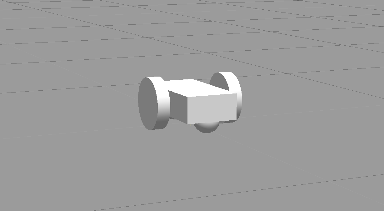
Great work till now! You will next add wheels to your robot. For this robot, you will require only two wheels. Each wheel is represented as a link and is connected to the base link (the chassis) with a joint.
You will first create the links for each wheel using the specifications given below and add that to your xacro file. The code provided above will act as a template. For each wheel, you will have a collision, inertial, and visual element along with the following properties/definitions -
link name- "SIDE_wheel", where the SIDE is either left or right.geometry- "cylinder" with radius 0.1 and length 0.05.originfor each element - [0, 0, 0, 0, 1.5707, 1.5707]massof each wheel - "5".- You can use the same
inertiavalues as the ones for the chassis for simplicity:
ixx="0.1" ixy="0" ixz="0"
iyy="0.1" iyz="0"
izz="0.1"
Once you have your links defined, you need to define the corresponding joints. The following code will create a joint between your left wheel (the child link) and the robot chassis (the parent link).
<joint type="continuous" name="left_wheel_hinge">
    <origin xyz="0 0.15 0" rpy="0 0 0"/>
    <child link="left_wheel"/>
    <parent link="chassis"/>
    <axis xyz="0 1 0" rpy="0 0 0"/>
    <limit effort="10000" velocity="1000"/>
    <dynamics damping="1.0" friction="1.0"/>
  </joint>
The joint type is set to "continuous" and is similar to a revolute joint but has no limits on its rotation. It can rotate continuously about an axis. The joint will have it's own axis of rotation, some specific joint dynamics that correspond to the physical properties of the joint like "friction", and certain limits to enforce the maximum "effort" and "velocity" for that joint. The limits are useful constraints in regards to a physical robot and can help create a more robust robot model in simulation as well. Here's a good resource to understand these limits better.
Using the above template, create the joint between the right wheel and the chassis!
SOLUTION:
- Child link
- Position (origin)
Excellent work! You can run the roslaunch command specified earlier and visualize your robot model in Gazebo!